Setup
Once, after assembly, set things up so that the computer knows which board is which arm, how far the servos move, and how the camera lenses distort the image. The arms are set up with the pinkrab command, and Hermit and the top camera with the pinkrab-umi command; all results are saved under ~/pinkrab/.
You can check how far the setup has come at any time.
pinkrab doctorEnvironment
/ python - 3.12.14
/ lerobot - 0.6.1
...
Servos
/ left - 7/7 responded, 30-34C
/ right - 7/7 responded, 30-33C
Before starting
Arms
/ arm boards named (which USB board is which arm) - left, right assigned
/ wall mount measured (base spacing, height above the desk) - mount.yaml
/ left arm calibrated (home pose held, every joint swept) - pinkrab_left.json
/ right arm calibrated (home pose held, every joint swept) - pinkrab_right.json
...
/ Environment looks good.pinkrab doctor changes nothing. It checks the environment, the connected boards, and the description, then shows for each step of this page whether it is done and the command to run for the remaining steps.
Servo board assignment
Section titled “Servo board assignment”The servo boards of the two arms are identical, so the device names the operating system assigns cannot tell which board is which arm. Once you assign them by plugging in in order, the same arm is recognized even after you unplug and replug a board.
pinkrab ports detectPort detection
Plug order is the only thing that tells the identical boards apart.
You will unplug these boards, then plug them in one at a time:
left -> right
[1] Unplug the USB cables of the left and right boards (others may stay), then press ENTER...
[2] Plug in the left board, then press ENTER...
[3] Plug in the right board, then press ENTER...
/ Saved to ~/pinkrab/ports.json
left tty.usbmodem5B7B0139551
right tty.usbmodem5B790834521Following the prompts, unplug both boards, then plug them in one at a time, left arm board first, then right arm board. If you find the arms swapped after the assignment, swap them with pinkrab ports swap.
Servo ID
Section titled “Servo ID”STS3215 servos all come from the factory with id 1, so to use them on the same bus each servo needs its own id written. The ids are 1–7 from the base outward, and are written through the arm’s board assigned in the previous step.
pinkrab setup-motors leftpinkrab setup-motors rightMotor numbering - this writes new ids into servo EEPROM.
Do not run it on servos that already work. It is for a servo that was
replaced, or an arm whose numbering is wrong or unfinished.
target: left tty.usbmodem5B7B0139551
order: gripper -> wrist_roll -> wrist_yaw -> wrist_flex -> elbow_flex -> shoulder_lift -> shoulder_pan
Connect only the servo named on screen, then press ENTER.
With more than one connected, they all take the id, or the wrong one does.
Proceed? Type 'y' to continue:
...Connect only the one servo of the joint shown on screen to the board and press ENTER, and that servo gets its id. If you write with two or more servos connected, all connected servos receive the same id, so always connect them one at a time. A servo that already has an id does not need one assigned again; enter an id again only when you want a different id or have replaced a servo. To enter the id of one specific joint directly, specify the joint with --joints.
pinkrab setup-motors left --joints wrist_roll # only the left arm wrist roll servopinkrab setup-motors right --joints wrist_flex wrist_yaw # two joints of the right armThe joint names are shoulder_pan, shoulder_lift, elbow_flex, wrist_flex, wrist_yaw, wrist_roll, and gripper. Even when you specify several joints, they are written in order from the gripper toward the base, regardless of the order you typed, so in the second example above you connect the wrist yaw first and the wrist flex afterward.
Drag to rotate
Servo response check
Section titled “Servo response check”pinkrab checkServo check (read-only)
left tty.usbmodem5B7B0139551
joint id ok position temp
shoulder_pan 1 / 2047 31C
shoulder_lift 2 / 3235 31C
elbow_flex 3 / 928 30C
wrist_flex 4 / 2128 30C
wrist_yaw 5 / 3112 34C
wrist_roll 6 / 1999 32C
gripper 7 / 2609 33C
right tty.usbmodem5B790834521
...
/ All servos responded on 2 arm(s).It sends a signal to the 7 servos of each arm in turn and shows the response, the current position, and the temperature. The servos are daisy-chained from the base outward, so if a middle connection is missing, every servo after it stops responding; in that case check reports the first joint that did not respond, so check that joint’s cable first. If it reports that several servos respond at once, a servo without an id is still left, so go back to the Servo ID step.
Mount dimensions
Section titled “Mount dimensions”pinkrab mountWall mount
Two measurements say where the arms are; everything else in mount.yaml
is derived. Millimetres, Enter keeps the current value.
1. between the two arm bases, centre to centre
2. from the desk surface up to the top of a base - the flat face
its plate, its beam and the cap over the first servo share
distance between the two arm bases, centre to centre, in mm [480]:
height of a base's top face above the desk, in mm [180]:
/ Written to ~/projects/pinkrab/src/pinkrab_description/config/mount.yaml
arms 480 mm apart, at y = +240.0 / -240.0 mm
base top 180 mm above the desk
The workspace URDF is expanded again by whatever next needs it.Enter the two actual mount dimensions on the desk in mm. The defaults are a spacing of 480 mm and a height of 180 mm; if you mounted the arms at a different spacing or height, enter the values measured with a tape measure. Pressing only Enter leaves the current value as is.
- The distance between the two arm base centers. Measure between the shoulder_pan axes of the two arms.
- The height from the desk surface to the top of the base. Measure up to the flat top surface formed together by the base plate, the beam, and the first servo’s cover.
The values are saved in src/pinkrab_description/config/mount.yaml.
These values determine where the two arms are in the desk coordinate frame, and inverse kinematics and the simulation use the same values.
Arm calibration
Section titled “Arm calibration”Calibration is done separately for each arm: you hold the arm in the home pose, start, and then move every joint from end to end so that the range each joint actually moves through is recorded in the servo. Clear the space the wall-mounted arm will move in first.
pinkrab calibrate leftpinkrab calibrate right- When it starts, the torque is released and you can move the arm by hand.
- Hold the arm in the home pose in the figure below, close the gripper, and press ENTER.
- Move each joint slowly from one end to the other, one at a time, and press ENTER when you have finished all of them.
Drag to rotate
The home pose is as follows.
- shoulder pan: the shoulder faces the front of the board.
- shoulder lift: the upper arm is tilted back and laid right above the top surface of the base.
- elbow flex: the forearm is folded forward and overlaps the upper arm.
- wrist flex: the wrist yaw bracket is centered so it tilts neither way.
- wrist yaw: the wrist is turned until it touches the wall of the bracket opening.
- wrist roll: the gripping surface is perpendicular to the wall, and the claw is on the outside.
You must move every joint all the way, including wrist roll. The wrist roll stops at ±175°, where the stops printed on the claw and the wrist meet, and the ends found in calibration become the servo’s limit values as they are. The results are saved per arm in ~/pinkrab/calibration/robots/pinkrab_follower/.
Wrist cameras
Section titled “Wrist cameras”The wrist cameras of the two arms are also the same model, so plug them in one at a time following the prompts to assign which camera is which arm.
pinkrab cameras Naming the follower arm cameras by their USB sockets, one plug at a time.
UNPLUG both follower arm cameras - then press Enter
...Next, measure the lens for each arm. Print the ChArUco board below at actual size on A4, attach it to a flat board, and show it in front of the camera while changing its distance and angle. Usable scenes are saved automatically, and when enough have accumulated, fit computes the lens values.
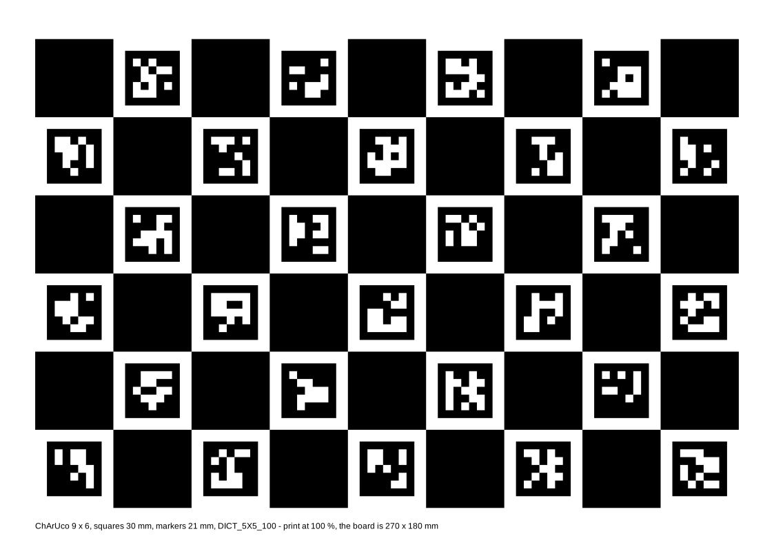
pinkrab lens capture leftpinkrab lens fit leftpinkrab lens capture rightpinkrab lens fit right follower_left: rms 0.697 px over 30 views (worst 0.94 px), seen out to 75 deg off axis
f 538.0 / 539.6 px/rad, centre (947.5, 578.9), k -0.0481, +0.0121, -0.0138, +0.0038
image circle 1473 px across, centre (928, 592)
against left: lens axis -13.9, -26.5 px, f -0.8 px/rad (-0.1 %)
written: ~/pinkrab/lens.yamlHermit
Section titled “Hermit”Hermit is set up in the same order as the arms.
pinkrab-umi setup-motor umi_left # new servos only, connected one at a timepinkrab-umi setup-motor umi_rightpinkrab-umi detect # assign by plugging in the left hand board, then the right hand boardpinkrab-umi check umi_leftpinkrab-umi check umi_rightpinkrab-umi calibrate umi_leftpinkrab-umi calibrate umi_rightpinkrab-umi cameras # plug in one at a time following the prompts to assign[1] Unplug the USB cables of the umi left and umi right boards (others may stay), then press ENTER...
...Hermit’s servo does not move the jaw and only reads how far the jaw is open, so calibration records only the servo positions with the jaw fully closed and with it opened all the way. The lens is measured the same way as for the wrist cameras.
pinkrab-umi lens capture leftpinkrab-umi lens fit leftpinkrab-umi lens capture rightpinkrab-umi lens fit right left: rms 0.560 px over 30 views (worst 0.99 px), seen out to 88 deg off axis
f 538.8 / 540.4 px/rad, centre (961.4, 605.4), k -0.0418, +0.0004, -0.0040, +0.0007
image circle 1553 px across, centre (962, 604)
against follower_left: lens axis +13.9, +26.5 px, f +0.8 px/rad (+0.1 %)
written: ~/pinkrab/lens.yamlTop camera
Section titled “Top camera”The top camera is the same module as the gripper cameras, so it is told apart by the USB socket it is plugged into. Following the prompts, unplug only the top camera and plug it back in, and that socket is assigned to the top camera; the gripper cameras may stay plugged in.
pinkrab-umi cameras --top Naming the top camera by its USB socket - the gripper cameras may stay plugged in.
UNPLUG the top camera - then press Enter
...The lens is also measured with the same ChArUco board. The top camera needs its lens values measured to compute marker poses, so the collection screen does not unlock markers before they are measured. Lift the board off the desk, tilt it 30–45° in various directions, and show it close and far, moving it all the way to the screen corners.
pinkrab-umi lens capture toppinkrab-umi lens fit top top camera: rms 0.465 px over 20 views (worst 0.67 px)
f 605.2 / 608.2 px (+-0.19%), centre (1045.8, 636.5), k +1.9460, +2.4231, -0.0005, +0.0003, +0.3098, +2.0318, +2.2415, +0.5145
it started from f 603.7 / 606.7, centre (1045.7, 636.5): f +0.25 %, centre +0.1, -0.0 px
written: ~/pinkrab/lens.yaml - the live view solves with it from its next startWhile measuring, turn off other programs that use the top camera (pinkrab-umi live, the collection screen in studio). If you change the lens, clear ~/pinkrab/lens/top and measure again.
Finally, run pinkrab doctor again to confirm that every item is done.